Optical Component Standards Explained: GJB, ISO, and MIL Standards in One Guide
When it comes to optical component inspection standards, many engineers and buyers are still confused by terms such as GJB, ISO, and MIL standards. Which one should be used? How do they differ? And how can they be compared?
Anyone working in optics will eventually encounter these standards.
You purchase a lens with a surface figure specification of λ/4 PV. The supplier asks, “According to which standard?” and suddenly you’re unsure.
You deliver a batch of prisms, and the customer requires compliance with MIL-PRF-13830. However, your internal documents only reference Chinese military standards (GJB), leaving you wondering how the two systems correspond.
Situations like these occur every day in the optical industry.
This article explains the origins, key contents, and major differences between GJB (Chinese Military Standards), ISO Standards, and MIL Standards, helping you understand how they describe and evaluate optical components.
1. Where Did These Standards Come From?
1.1 MIL Standards: The Foundation of Modern Optical Inspection
MIL (Military) Standards were developed by the U.S. Department of Defense for military procurement and quality assurance.
The most influential optical standards include:
- MIL-PRF-13830 – Optical Components Performance Specification
- MIL-PRF-19884 – Optical System Specifications
- MIL-C-48497 – Optical Coating Specifications
These standards originated during World War II when large-scale military demand required consistent optical quality control. During the Cold War, the standards evolved further and eventually became widely adopted throughout the global optical industry.
Among them, MIL-PRF-13830 introduced the famous Scratch-Dig system for evaluating surface quality. Even today, many commercial optical manufacturers continue to use this system when no alternative standard is specified.
As a result, MIL standards have become one of the most widely recognized “languages” in global optics.
1.2 ISO Standards: The International Language of Civilian Optics
ISO optical standards are developed by ISO Technical Committee 172 (TC172), which focuses on optics and photonics.
Important standards include:
- ISO 10110 Series – Optical Drawing and Documentation Standards
- ISO 14999 Series – Interferometric Test Methods
- ISO 9022 Series – Environmental Testing Methods
The ISO 10110 series is the most commonly encountered standard for optical engineers.
It defines how optical specifications should be represented on engineering drawings, using standardized notation formats for surface quality, material properties, coatings, and other optical parameters.
Leading European optical companies such as Zeiss, Leica, and Schott typically use ISO 10110 as their primary documentation standard.
1.3 GJB Standards: China’s Military Optical Standard System
GJB (Guojia Junyong Biaozhun, National Military Standards) are mandatory standards used within China’s defense industry.
Important optical standards include:
- GJB 2485 – Technical Requirements for Optical Components
- GJB 1327 – Environmental Testing Methods for Optical Instruments
- GJB 5640 – General Specifications for Optical Coatings
- GB/T 2831 – Surface Figure Error Standards
Historically, the GJB system was influenced by Soviet GOST standards. Over time, it gradually incorporated concepts from ISO and MIL standards, creating a hybrid framework tailored to China’s industrial requirements.
2. How Do These Standards Describe the Same Optical Properties?
The quality of an optical component is generally defined by:
- Surface Figure Accuracy
- Surface Quality (Scratch & Dig)
- Surface Finish
- Refractive Index Homogeneity
- Wedge and Centration Errors
- Wavefront Error
Let’s compare how each standard handles these parameters.
2.1 Surface Figure Accuracy
Surface figure accuracy describes the deviation between the actual optical surface and its ideal design form.
MIL Standards
MIL standards typically express surface figure using interference fringes (N).
Under standard test wavelengths (commonly 546 nm or 632.8 nm), one fringe corresponds approximately to a λ/2 peak-to-valley (PV) surface deviation.
Therefore:
N Fringes ≈ N × λ/2 (PV Error)
ISO 10110-5
ISO uses the notation:
3/ N × ΔN
Where:
- N = Power (low-frequency error)
- ΔN = Irregularity (high-frequency error)
Although similar to MIL terminology, the definitions and reference wavelengths must be carefully verified before making direct comparisons.
GB/T 2831 and GJB Standards
Chinese standards also use fringe counts to characterize surface figure errors.
However, historical versions may differ slightly in fringe counting methods and testing procedures. Always verify the applicable revision and measurement conditions.
2.2 Surface Quality (Scratch and Dig)
This is where the largest differences exist among the three systems.
MIL-PRF-13830 Scratch-Dig System
Surface quality is expressed as:
Scratch / Dig
Examples:
- 10-5
- 20-10
- 40-20
- 60-40
Scratch
The scratch number does not represent an actual physical width.
Instead, it is determined by visual comparison with calibrated reference standards.
Smaller numbers indicate stricter requirements.
Dig
The dig number represents the allowable defect diameter in hundredths of a millimeter.
For example:
- Dig 10 = 0.10 mm maximum defect diameter
- Dig 20 = 0.20 mm maximum defect diameter
Typical applications:
- Laser optics: 10-5
- Precision imaging optics: 20-10
- General industrial optics: 40-20 or 60-40
One limitation of the MIL system is that scratch grading remains somewhat subjective because it relies on visual inspection.
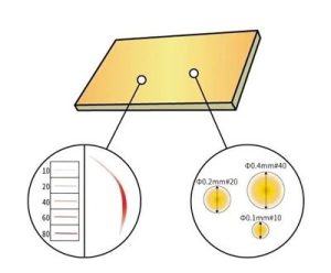
ISO 10110-7 Surface Imperfections
ISO 10110-7 adopts a more quantitative approach.
Instead of visual comparison, defects are specified using measurable physical dimensions, including:
- Scratch length
- Scratch width
- Pit diameter
- Coating defects
- Defect density
This method provides greater repeatability and traceability but requires more sophisticated inspection equipment.
GJB and Chinese Standards
Traditional Chinese optical standards often describe surface quality using:
- Surface Finish Grades
- Surface Roughness (Ra)
However, these parameters characterize microscopic roughness rather than visible scratches and digs.
For export projects and high-end optical manufacturing, many Chinese companies now directly adopt the MIL Scratch-Dig system or specify both systems simultaneously.
2.3 Refractive Index Homogeneity
Optical homogeneity describes variations in refractive index throughout the optical material.
All three systems recognize its importance, but testing methods and acceptance criteria may differ depending on application requirements.
High-performance laser systems and precision imaging applications generally require tighter homogeneity tolerances.
2.4 Wedge Angle and Centration Error
Wedge angle and centration error describe the alignment of optical surfaces relative to the optical axis.
MIL, ISO, and GJB standards all provide methods for evaluating these parameters, though the notation and reporting formats differ.
2.5 Transmitted Wavefront Error (WFE)
Wavefront error has become increasingly important in modern high-performance optical systems.
Unlike surface figure alone, WFE evaluates the overall optical performance after light passes through the component.
Today, many advanced optical systems specify wavefront error directly as a system-level performance requirement.
3. Common Misunderstandings
Misunderstanding #1: Does MIL Fringe Count Represent PV or RMS?
MIL fringe values represent Peak-to-Valley (PV) error.
The conversion is approximately:
PV = N × λ/2
Meanwhile, optical designers frequently use RMS values.
Depending on the surface profile:
RMS ≈ PV / 3.5 to PV / 5
Comparing PV and RMS directly can lead to serious misunderstandings.
Always verify which metric is specified.
Misunderstanding #2: Can Scratch-Dig Be Converted to ISO 10110-7?
Only approximately.
MIL Scratch-Dig is based on visual appearance, whereas ISO 10110-7 uses measurable physical dimensions.
Although rough equivalencies exist, no exact conversion formula is universally accepted.
Misunderstanding #3: What If a Customer Requires Both GJB and MIL Compliance?
This is common in military-civilian integration projects and export programs.
Recommended practice:
- Follow the stricter requirement whenever conflicts exist.
- Clearly define testing methods and equipment.
- Record measurement wavelength and environmental conditions.
- Use dual-standard specifications on engineering drawings whenever possible.
4. Which Standard Should You Use?
MIL Standards
Best suited for:
- Military optics
- Defense procurement
- Laser optics
- International optical manufacturing
ISO Standards
Best suited for:
- International commercial projects
- European customers
- Engineering documentation
- Digital quality management
GJB Standards
Best suited for:
- Chinese military projects
- Domestic defense programs
- Government procurement
5. Practical Recommendations for Optical Engineers
Always Identify the Referenced Standard First
The same numerical value can have completely different meanings under different standards.
Specify Measurement Conditions
For surface figure accuracy, always define:
- Test wavelength
- PV or RMS
- Reference surface
- Measurement method
Consider ISO 10110-7 for High-End Applications
For laser systems, medical optics, and precision imaging, quantitative defect specifications are often preferable to visual Scratch-Dig grading.
Avoid Assumptions in Cross-Standard Procurement
Whenever multiple standards are involved, define:
- Primary governing standard
- Test methods
- Acceptance criteria
- Conflict-resolution rules
Prepare for Dual-Standard Requirements
As China’s optical manufacturing industry continues to advance, many high-end projects increasingly reference both GJB and ISO standards simultaneously.
Engineers who understand both systems will be better prepared for future international projects.
Conclusion
MIL, ISO, and GJB standards ultimately describe the same objective: defining and verifying the quality of optical components.
The differences arise from historical development, application environments, and regional practices.
Understanding how these standards relate to one another is not only essential for inspection and acceptance—it is also fundamental to optical design, supply chain management, and quality control.
The better you understand standards, the better optical components you can design, manufacture, and deliver.